
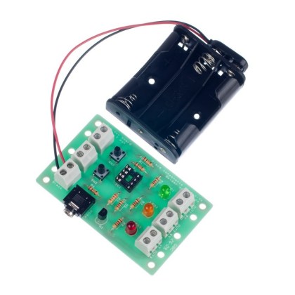
With its low part count this easy build timer project makes a good introduction to electronics. The timer uses a resistor capacitor network to provide a time delay of between 1 second and 4 minutes, which is set by the PCB mount variable resistor. When the button is pressed the LED changes from red to green, then at the end of the time interval it turns red.
This product is also available in retail packaging making them an ideal gift. Click here to view the retail version.
Note:
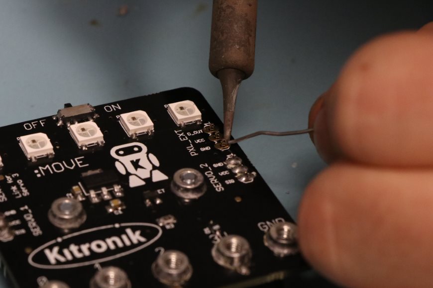
- This kit requires some soldering.
Features:
- Easy build timer kit.
- When the time set has been reached the LED changes colour.
- The time delay can be adjusted via the variable resistor.
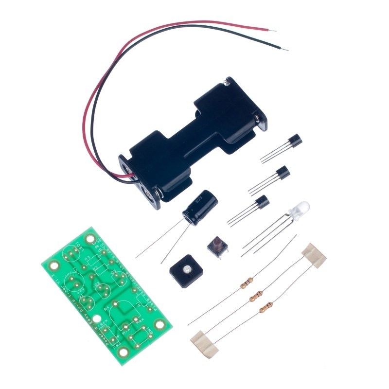
Contents:
- 1 x 2AA Battery Cage.
- 1 x 47Ω Resistor.
- 2 x 10KΩ Resistors.
- 1 x 1MΩ Potentiometer.
- 1 x Capacitor, Electrolytic, 10V, 1 mF.
- 1 x BC558 PNP Transistor.
- 1 x Tri colour 5mm diffused LED – 650mCd.
- 1 x 6mm PCB Mount Tactile Switch 9.5mm Height.
- 1 x Easy Build Timer PCB
Dimensions:
- PCB Length: 54mm.
- PCB Width: 26mm.
Requires:
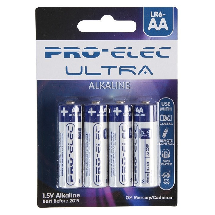
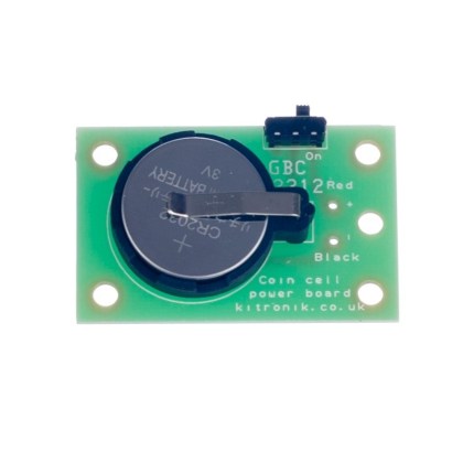
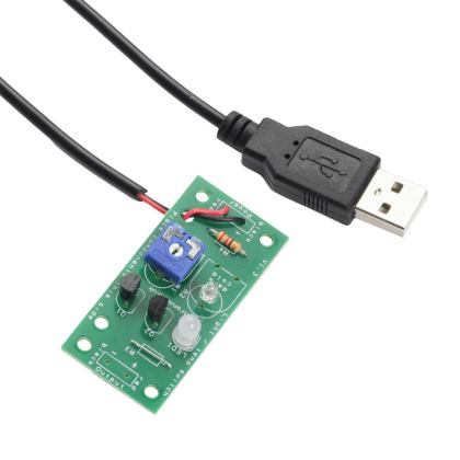
- 2 x AA batteries, available separately. Alternatively, it can be powered by our easy build coin cell power board.
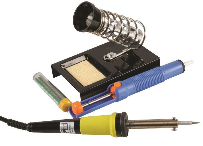
- Soldering Iron.
- Solder.
- Wire Cutters.


Reviews
There are no reviews yet.