

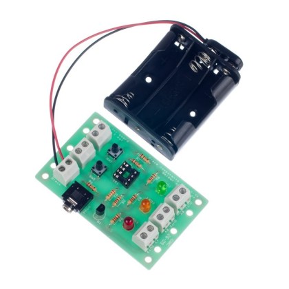
This kit can be used to make a shed or room alarm when mounted on the top of a door, drawers or any other object with a moveable opening. It can also be used by replacing the micro switch with a magnetic door contact.
A micro switch acts as a trigger mechanism and is armed / disarmed by a seperate sliding switch. The door’s movement is detected by a micro switch mounted onto a door or object with a lid. A timer provides an entry delay during which the system can be disarmed by the slide switch, whilst a separate timer silences the alarm after two minutes. Both of these timers are implemented via a 556 dual timer IC.
The alarm can be further enhanced by using a simple key switch for arming / disarming or by replacing the micro switch with a magnetic door contact switch to activate it. The board, battery pack & buzzer can be placed into a box designed by the student.
Features:
- Can be enhanced with a key switch to arm/disarm.
- Can be enhanced by replacing the micro switch with a magnetic door contact switch.
- Entry delay for disarming.
Contents:
- 1 x PP3 Battery Clip Lead (Heavy Duty).
- 1 x 4xAA Battery Cage with Clip.
- 1 x Miniature DPDT Slide Switch.
- 1 x NE556 Dual Timer IC.
- 1 x IC Socket 14 Pin.
- 1 x Piezo Buzzer (with Drive).
- 4 x Capacitor, Ceramic, 50V, 10nF.
- 2 x 100uF Cap Low Leakage.
- 3 x 10KΩ Resistor.
- 1 x 220KΩ Resistor.
- 2 x 1.2MΩ Resistor.
- 1 x Micro Switch with Medium Lever.
- 1 x Red 5mm Diffused LED – 275mCd.
- 1 x 330Ω Resistor.
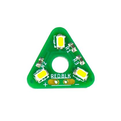
- 1 x Alarm Project Kit PCB.
Possible applications include:
- Adding an alarm to a cookie/biscuit tin.
- Adding an entry alarm to a door.
Dimensions:
- PCB Length: 51mm.
- PCB Width: 41.5mm.
Requires:
- 4 x AA Batteries.
Resources:
-
Click here to download the essential information.

-
Click here to download the full teaching resources.
This kit is supplied in a simple grip seal bag.
Note:
This is an educational kit and should not be used to secure anything of value.

Reviews
There are no reviews yet.