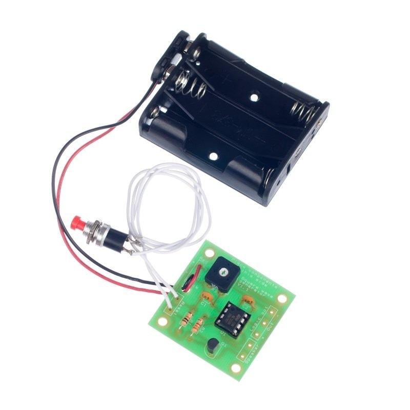
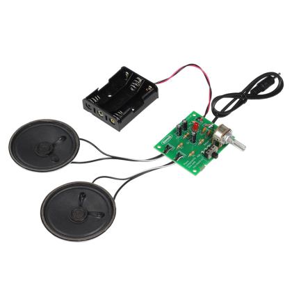
This kit is perfect for GCSE students needing to use a 555 timer in its astable mode, where it produces a square wave output. The frequency of which is adjustable via the variable resistor. The board has a choice of two outputs. The logic output can be used to drive another IC or a speaker can be connected so the tone is heard (e.g. a door bell).
The push button switch connects to the reset line such that the IC is only active when the button is pressed.
Features:
- The 555 Timer Astable (Tone Generator) Kit produces a square wave output.
- The frequency of the aquare wave is adjustable via the variable resistor.
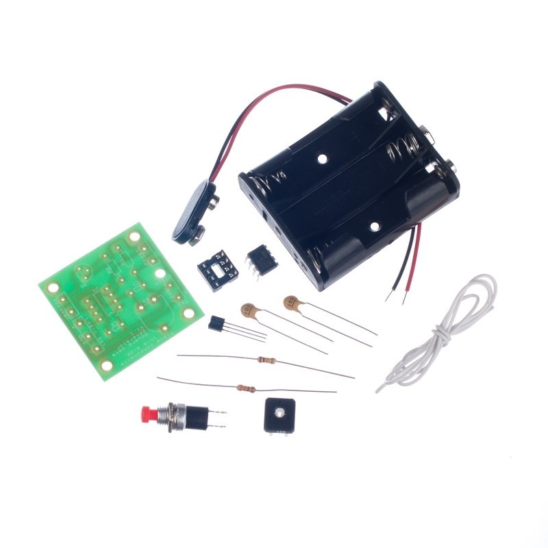
Contents:
- 1 x 555 Timer IC.
- 1 x 8 Pin IC Holder.
- 1 x 3.3KΩ Resistor.
- 1 x 10KΩ Resistor.
- 1 x 47KΩ Potentiometer.
- 2 x 10nF Ceramic Capacitors.
- 1 x BC547 NPN Transistor.
- 1 x Push To Make Switch.
- 1 x PP3 Clip Lead.
- 1 x 3AA Battery Holder.
- 0.5m Connecting Wire
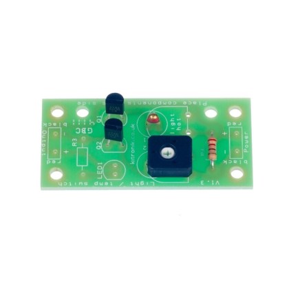
- 1 x Tone Generator PCB
Dimensions:
- PCB Length: 40mm.
- PCB Width: 40mm.
Requires:
Resources:
Note:
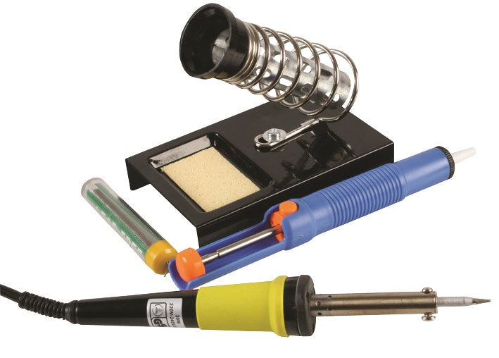
- This kit requires soldering.
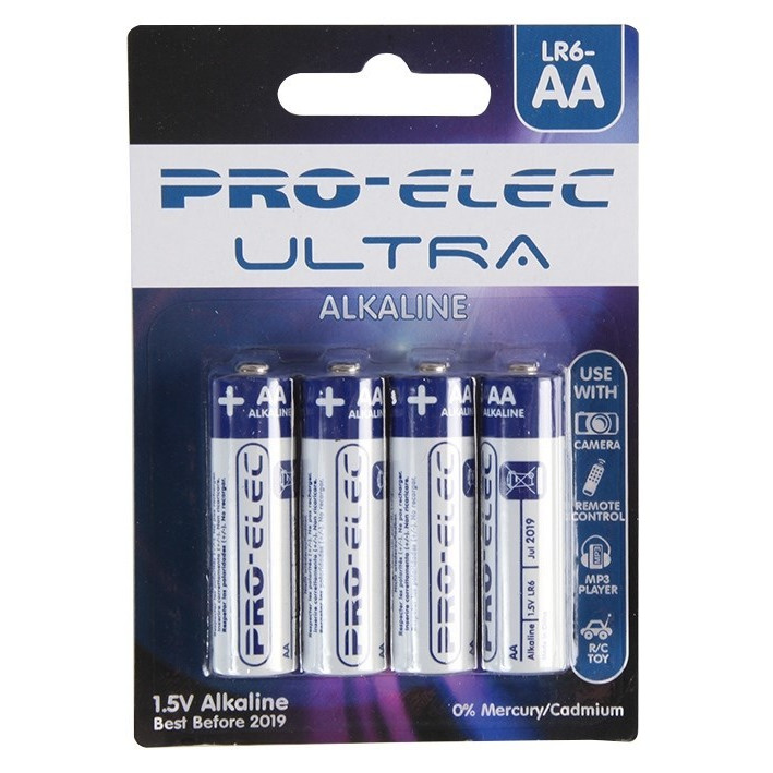
- Requires x 3 x AA Batteries. and depending upon desired use a speaker, both available separately.


Reviews
There are no reviews yet.