0
Your Cart
0
Your Cart

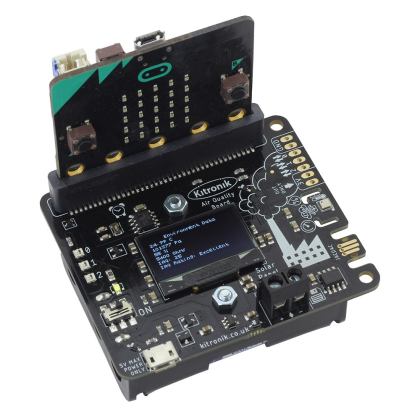
Looking to do more with your BBC micro:bit? Unlock its potential with this ‘pre-built’ version of our Edge Connector Breakout Board! This breakout board has been designed to offer an easy way to connect additional circuits and hardware to the pins on the edge of the BBC micro:bit. It provides access to all of the BBC micro:bit processor pins allowing a lot of extra functionality to be added. The datasheet (below) includes a helpful diagram explaining the function of every pin on the BBC micro:bit.

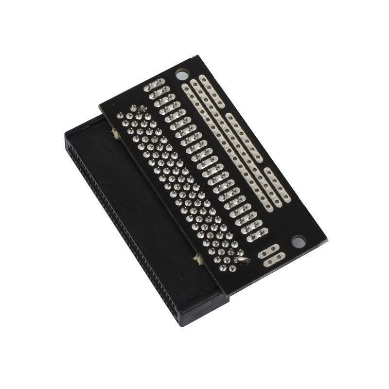
This Edge Connector Breakout Board for the BBC micro:bit gives access to all of the important pins on the bottom edge of the BBC micro:bit. 21 pins are broken out in total; providing additional I/O lines, direct access to buttons A and B, the LED matrix outputs and the I2C bus. Please refer to the datasheet below for more details.

The BBC micro:bit pins are broken out to a row of pin headers. These provide an easy way of connecting circuits using jumper wires. The SCL and SDA pins are separated at the edge of the board (solder pads) providing easy identification. The PCB includes a prototyping area with 3V, 0V and unconnected rows that can be soldered to. This allows the easy connection of switches, sensors and any pull-up or pull-down resistors etc. as required.

If you are looking for inspiration, look no further than these examples using the Edge Connector for the BBC micro:bit:
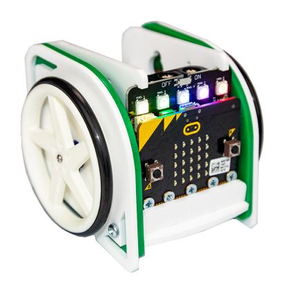
To use the breakout board the BBC micro:bit should be inserted firmly into the connector as shown below:

Kitronik Edge Connector Breakout Board for BBC micro:bit - showing micro:bit

Note:

Features:

  • Features a dedicated pin strip for quick and easy prototyping.
  • Breaks out 21 pins from the edge of the BBC micro:bit.
  • Dedicated prototyping area with 3V and 0V rows.
  • Labelled pins and clear straightforward documentation.

Contents:

  • 1 x Edge Connector Breakout Board for the BBC micro:bit, Pre-built.

Possible applications include:

Dimensions:

  • Length: 60mm.
  • Width: 40mm.
  • Height: 11.8mm.

Video:


Requires:

Accessories:

Resources:

Documents & downloads

Related resources

Reviews

There are no reviews yet.

Be the first to review “Kitronik Edge Connector Breakout Board for BBC micro:bit – Pre-built”

Your email address will not be published. Required fields are marked *

Questions and answers

    What would be the recommendation for connecting a 12LED Neopixel ring to this board? Would it be easy/functional to connect it to one of the servo connections? Or would it be better to connect to the header pins? If so, are there specific header pins that we would need to connect it to? Thanks!
  1. 0 votes
    Q What would be the recommendation for connecting a 12LED Neopixel ring to this board? Would it be...... Read more
    Asked by Tim on May 20, 2019 12:00 am
    Answered by the admin Hi Tim,

    Thank you for your question, you should be able to connect them up with jumper cables. I would recommend connecting from Pin 0 as that is the default for the neo pixels.

    Best Regards

    Cullen
  2. Where is the ground?
  3. 0 votes
    Q Where is the ground?
    Asked by Josh on March 18, 2019 12:00 am
    Answered by the admin Hi Josh,

    Thank you for your question, the pin labelled 0V is the Ground Pin.
  4. How would I connect 2 motors on the single 3V output when i want them to work seperatly?
  5. 0 votes
    Q How would I connect 2 motors on the single 3V output when i want them to work seperatly?
    Asked by dennis on January 25, 2019 12:00 am
    Answered by the admin Hi Dennis, Unfortcunately the micro:bit can only provide a very small amount of current. As such you shouldn't try to drive something such as a motor directly from the micro:bit, instead you would be better using something like our Motor Driver Board
    or All in one Robotics Board
    to drive motors.
  6. Please could you provide an stl file of this breakout board? And possibly also with the microbit mated.Thanks
  7. 0 votes
    Q Please could you provide an stl file of this breakout board? And possibly also with the microbit...... Read more
    Asked by James on September 10, 2018 12:00 am
    Answered by the admin Hi James,

    Thank you for your question I am afraid we do not have .stl files for this product that we can supply out to the public.

    Best Regards

    Cullen
  8. Could you please create a Fritzing part (.fzb) of this breakout board please?
  9. 0 votes
    Q Could you please create a Fritzing part (.fzb) of this breakout board please?
    Asked by stuart on July 19, 2017 12:00 am
    Answered by the admin Hello Stuart, I have looked into this and unfortunately this isn't something we are able to do currently as we don't have anyone who is able to create the part. However it may be something that we can revisit in the future.
  10. Do I remove the green rubber stuff from the breakout board?
  11. 0 votes
    Q Do I remove the green rubber stuff from the breakout board?
    Asked by Simon Law on July 13, 2017 12:00 am
    Answered by the admin Hi Simon, Yes you should peel this off before using the breakout board. It is there only to protect the pads when the board is manufactured.
  12. You don't populate pins 19/20 with male headers, but they are needed for i2c connection. Why is that?
  13. 0 votes
    Q You don't populate pins 19/20 with male headers, but they are needed for i2c connection. Why is t...... Read more
    Asked by Romilly Cocking on March 7, 2017 12:00 am
    Answered by the admin Hello Romilly, The rationale behind the design is this: The micro:bit has 21 connections, however it is not possible to buy a 2 x 21 section of pin header. The 2 x 20 way is however readily available, so the board was designed with the most common connections going to the 20 way break out. As for the two I2C pins, we wanted to include these for more advanced users of the board, but placed them to one side. Anyone that wants to connect to these pins can either permanently solder in to them or add their own pin header.
  14. Can you supply a blank template inventor board diagram for students to use in class. We have received our kits and are delighted with them.
  15. 0 votes
    Q Can you supply a blank template inventor board diagram for students to use in class. We have rece...... Read more
    Asked by Stuart on December 21, 2016 12:00 am
    Answered by the admin Hi Stuart, I believe you are wanting a pin out of the edge connector board, you can use the datasheet page 1 and 2 which shows the pins on the micro:bit and a digital copy of the edge connector board.
  16. Please can you supply an actual data sheet for the 40 way right angle connector from its manufacturer.Many thanks
  17. 0 votes
    Q Please can you supply an actual data sheet for the 40 way right angle connector from its manufact...... Read more
    Asked by simon chubb on May 16, 2016 12:00 am
    Answered by the admin I am currently looking to obtain the datasheet for this and get it placed on the website. In the meantime what information are you looking for and I will try to find this out?
To submit a question, please login or create an account