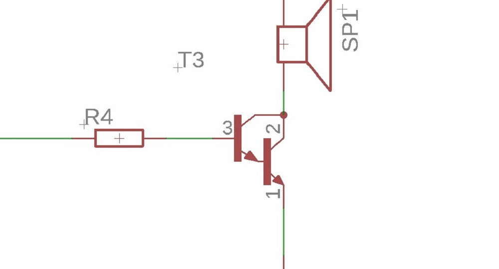
A Darlington pair is two transistors that act as a single transistor but with a much higher current gain. This mean that a tiny amount of current from a sensor, micro-controller or similar can be used to drive a larger load. An example circuit is shown below:

The Darlington Pair can be made from two transistors as shown in the diagram or Darlington Pair transistors are available where the two transistors are contained within the same package.
What is current gain?
Transistors have a characteristic called current gain. This is referred to as its hFE. The amount of current that can pass through the load in the circuit above when the transistor is turned on is: Load current = input current x transistor gain (hFE) The current gain varies for different transistors and can be looked up in the data sheet for the device. For a normal transistor this would typically be about 100. This would mean that the current available to drive the load would be 100 times larger than the input to the transistor.
Why use a Darlington Pair?
In some applications the amount of input current available to switch on a transistor is very low. This may mean that a single transistor may not be able to pass sufficient current required by the load. As stated earlier this equals the input current x the gain of the transistor (hFE). If it is not possible to increase the input current then the gain of the transistor will need to be increased. This can be achieved by using a Darlington Pair. A Darlington Pair acts as one transistor but with a current gain that equals: Total current gain (hFE total) = current gain of transistor 1 (hFE t1) x current gain of transistor 2 (hFE t2) So for example if you had two transistors with a current gain (hFE) = 100: (hFE total) = 100 x 100 (hFE total) = 10,000 You can see that this gives a vastly increased current gain when compared to a single transistor. Therefore this will allow a very low input current to switch a much bigger load current.
Base Activation Voltage
Normally to turn on a transistor the base input voltage of the transistor will need to be greater than 0.7V. As two transistors are used in a Darlington Pair this value is doubled. Therefore the base voltage will need to be greater than 0.7V x 2 = 1.4V. It is also worth noting that the voltage drop across collector and emitter pins of the Darlington Pair when the turn on will be around 0.9V Therefore if the supply voltage is 5V (as above) the voltage across the load will be will be around 4.1V (5V – 0.9V)
Other resources
This article is listed in the resource section of the web site within the understanding electronics section. You may be interested in other similar resources:
- How A Transistor Works.
- How to identify components.
- The Interactive Learn & Test Zone, a place to learn about and test yourself on electronics.
See it in a real project
We have two electronic kits which utilise a Darlington pair to allow an output current of up to half an Amp to be controlled:
Download a pdf version of this page here ![]() Learn more about the author read more » If you found this article helpful and you would like to receive product updates and free electronic resources from us then sign up to our newsletter here. We hate spam too and promise to never sell or share your email address, and you can unsubscribe at any time.
Learn more about the author read more » If you found this article helpful and you would like to receive product updates and free electronic resources from us then sign up to our newsletter here. We hate spam too and promise to never sell or share your email address, and you can unsubscribe at any time.