

Note:
This board has been redesigned and improved and is now available in a more compact version here.
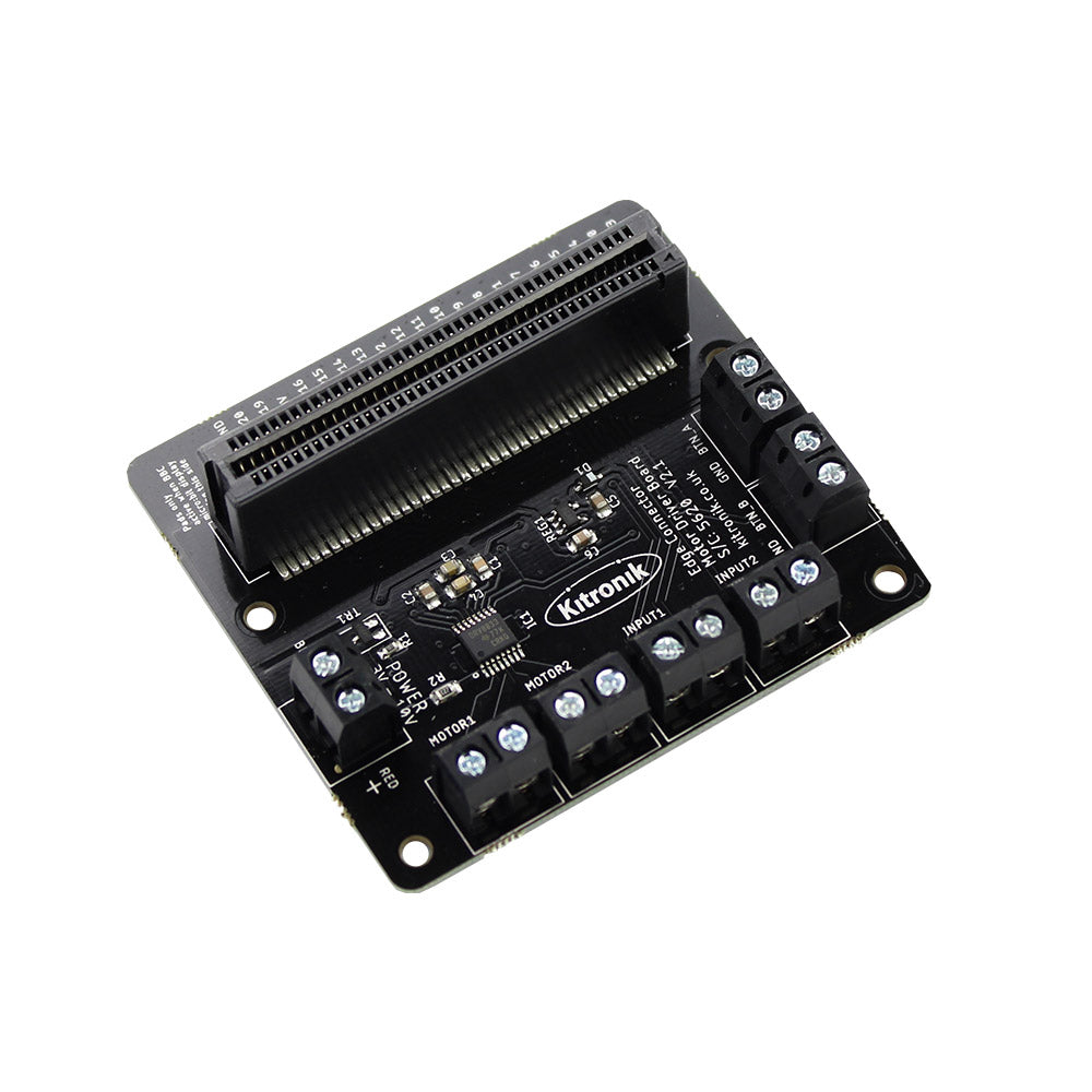
This motor driver board for the BBC micro:bit allows two motors to be driven simultaneously with forward, reverse & stop control, making it ideal for designs such as buggies. It is based on the DRV8833 motor driver IC, which has built-in short circuit, over current and thermal protection.
The board includes an integrated Edge Connector slot for your BBC micro:bit to easily slot into. It also features external connections to the button A and button B inputs. This allows additional switches/inputs to be connected to the motor driver board and the state of these can then be read by the BBC micro:bit.

There are 2 additional inputs/outputs. These can be used for connecting a range of parts and can be used in either digital or analogue modes.
The board also produces a regulated 3V supply that is fed into the 80 way connector to power the inserted BBC micro:bit, removing the need to power the BBC micro:bit directly
The board has been designed so that the BBC micro:bit can be inserted either way around (facing forward or backwards) however if you wish to use the broken out pins the LED matrix on the BBC micro:bit must be facing them.
Features:
- Drive 2 motors with full forward, reverse and stop control.
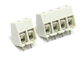
- Terminal blocks for easy connection of motors and inputs.
- 4 inputs (2 analogue inputs and 2 provide external connections to Buttons A and B as inputs).
- Includes Edge Connector for the BBC micro:bit to slot into.
- Provide regulated power to the BBC micro:bit.
- Access the other BBC micro:bit pins easily and conveniently.
- Ideal for designs such as buggies and other robotics projects.
- Operating Voltage of 3V to 10V.
Contents:
- 1 x Edge Connector Motor Driver Board for the BBC micro:bit – V2.
Dimensions:
- Length: 67mm.
- Width: 61mm.
- Height: 18mm.
Video:
Requires:
- 1 x BBC micro:bit.
- 3V – 10V Power Supply.
- 2 x DC Motors (that are compatible with the power supply used).
- 1 x Flat-headed Terminal Screwdriver.


Electron –
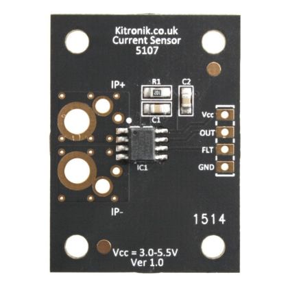
My latest use of the Motor Driver Board is to control a three wheeled vehicle which has two motors taking 300 mA, well within the 1.5A available. I use the P1 and P2 inputs for sensors for tracking a light source, and line follower. In addition it is guided by a radio link to a hand carried micro:bit (tipped to steer). And I am about to use the Bitty Controller from http://www.bittysoftware.com/apps/bitty_controller.html
on my tablet to steer it using bluetooth (the micro:bit does not let you use radio and bluetooth together). I plan to add a proximity sensor and use the Button A and Button B inputs for sensors.
Using the makecode.microbit.org site “Lets Code” blockcode click on Advanced, then + ADD Package. In the Search area type Kitronik. Then click on Motor Driver Board and you will get a new set of blocks called Motor Driver in green. This gives you a block to select motor 1 or 2 the direction of travel and an “analogue” speed from 0 to 100 (fastest). This saves ,you a lot of coding to achieve the same thing. And there is a block to stop the motors.
The Motor Driver Board has an on board 3 V regulator which can supply up to 100 mA and I use this rather than the micro:bit 3V
terminal. I use the second MDB 3V and GND terminals to feed a LED which tells me when battery power is on as I was forgetting to switch it off.
All in all it has saved me a lot of time designing and building a motor power amplifier and it provides a handy socket for the micro:bit.
Sam –
An outstanding product that has brilliant application within schools!!